In previous posts, we have learned what is Kubernetes, and its involvement in DevOps Project. So, in this project, we will learn what is Infrastructure as Code(Iac) and how to implement it using Terraform.
The first time I had to build an environment manually, it took almost two days. I installed packages one by one, configured servers, updated firewall rules, and documented everything in a spreadsheet. A few weeks later, another environment was needed. I followed the same notes.
The result?
The new setup behaved differently from the original one.
That is exactly the kind of problem Infrastructure as Code (IaC) was created to solve.
Instead of depending on manual steps, memory, and documentation that quickly becomes outdated, teams write infrastructure requirements as code. The infrastructure can then be created, modified, tested, and reproduced whenever needed.
For modern DevOps teams running Kubernetes, IaC is no longer optional. It has become a standard way to manage both cloud infrastructure and Kubernetes configurations reliably.
Why Infrastructure as Code Became So Important
Think about managing hundreds of servers manually.
Every server must have:
- Operating system configuration
- Network settings
- Security groups
- Storage volumes
- User permissions
- Application dependencies
Now multiply that across development, testing, staging, and production environments.
Human errors become unavoidable.
A small mistake in one server can cause unexpected application failures that are difficult to troubleshoot later.
IaC solves this problem by making infrastructure predictable.
Instead of manually creating resources, you define them in code files and execute those files whenever an environment is needed.
The same code produces the same result every time.
What is Infrastructure as Code (IaC)?
Infrastructure as Code is a DevOps practice where infrastructure resources are defined using machine-readable configuration files.
These files describe exactly what should be created, including:
- Virtual machines
- Networks
- Storage
- Load balancers
- Kubernetes clusters
- Security policies
Rather than opening cloud dashboards and clicking buttons repeatedly, engineers write configuration files and deploy infrastructure automatically.
A simple example might look like this:
- Create 3 virtual machines
- Attach 100 GB storage
- Open port 443
- Create a Kubernetes cluster
- Deploy monitoring tools
Everything is written in code.
The infrastructure becomes version-controlled just like application source code.
Key Benefits of Infrastructure as Code
Consistency Across Environments
One of the biggest problems in IT operations is configuration drift.
You may hear developers say:
“It works on my machine.”
That usually happens because environments are not identical.
With IaC:
- Development environment matches production
- Testing environment matches staging
- Configurations remain standardized
The same code builds identical environments repeatedly.
Faster Deployments
Manual provisioning can take hours or even days.
IaC reduces this dramatically.
For example:
| Task | Manual Setup | IaC Setup |
|---|---|---|
| Create VM | 15 minutes | 1 minute |
| Configure Network | 20 minutes | Automated |
| Deploy Kubernetes Cluster | Several hours | Few minutes |
| Scale Infrastructure | Manual work | Automatic |
This speed allows teams to release features much faster.
Version Control and Audit Trail
IaC files are usually stored in Git repositories.
This provides several advantages:
- Track every change
- Review code before deployment
- Identify who made changes
- Roll back problematic updates
Many organizations treat infrastructure code exactly the same way they treat application code.
Kubernetes and Infrastructure as Code
When I first started working with Kubernetes, one thing stood out immediately.
Everything revolves around declarations.
Instead of giving Kubernetes detailed instructions about how to run applications, you simply describe the desired outcome.
Kubernetes then works continuously to achieve that state.
For example:
You can define:
- Run 3 application pods
- Expose them through a service
- Restart failed containers automatically
- Maintain application availability
Kubernetes handles the operational work behind the scenes.
This approach aligns perfectly with Infrastructure as Code principles.
Understanding Kubernetes Configuration
Kubernetes configuration is typically stored in YAML files.
These files describe resources inside the cluster.
Common Kubernetes resources include:
| Resource | Purpose |
|---|---|
| Pod | Runs containers |
| Deployment | Manages pod replicas |
| Service | Exposes applications |
| ConfigMap | Stores configuration data |
| Secret | Stores sensitive information |
| Persistent Volume | Provides storage |
| Ingress | Manages external traffic |
A deployment file might simply specify:
- Application image
- Number of replicas
- CPU limits
- Memory limits
- Network configuration
Once applied, Kubernetes continuously monitors the environment and keeps everything aligned with the desired state.
Why Store Kubernetes YAML Files in Git?
Many teams follow a GitOps approach.
In GitOps, Git becomes the single source of truth.
Whenever changes are needed:
- Update YAML files
- Commit changes to Git
- Review through pull requests
- Deploy automatically
This provides several benefits:
- Full change history
- Easier troubleshooting
- Better collaboration
- Faster recovery after failures
- Security auditing
When something breaks, engineers can quickly compare previous versions and identify what changed.
Popular IaC and Kubernetes Configuration Tools
Different tools manage different layers of the infrastructure stack.
Some provision cloud resources.
Others manage Kubernetes applications.
Let’s look at the most common ones.
Terraform
Terraform is one of the most widely used Infrastructure as Code tools.
It focuses on creating and managing infrastructure resources.
Before Kubernetes even exists, Terraform can create:
- AWS EC2 instances
- Amazon EKS clusters
- Google Kubernetes Engine (GKE)
- Azure Kubernetes Service (AKS)
- VPCs
- Subnets
- Security Groups
- Load Balancers
A common workflow looks like this:
- Write Terraform files
- Execute terraform plan
- Review proposed changes
- Execute terraform apply
- Infrastructure gets created automatically
Many organizations use Terraform as the foundation of their cloud infrastructure strategy.
Where Terraform Fits
| Layer | Managed By |
|---|---|
| Cloud Infrastructure | Terraform |
| Kubernetes Cluster | Terraform |
| Applications | Kubernetes/Helm |
Helm
After Kubernetes is running, applications must be deployed.
This is where Helm becomes extremely useful.
Helm acts as the package manager for Kubernetes.
Instead of maintaining dozens of YAML files manually, Helm packages them into reusable units called Charts.
A Helm chart can contain:
- Deployments
- Services
- ConfigMaps
- Secrets
- Ingress resources
Imagine deploying:
- Prometheus
- Grafana
- Jenkins
- Argo CD
Without Helm, managing all related YAML files becomes tedious.
With Helm, installation can often be completed using a single command.
Benefits of Helm
- Reusable templates
- Environment-specific values
- Easier upgrades
- Simple rollbacks
- Reduced YAML duplication
This is one reason Helm is heavily used in production Kubernetes environments.
Kustomize
Not every team wants template-based deployments.
Sometimes teams simply want to customize existing Kubernetes manifests.
Kustomize was designed for this purpose.
Instead of creating templates, Kustomize applies overlays on top of existing YAML files.
For example:
Base configuration:
- 2 replicas
- Standard resources
Production overlay:
- 10 replicas
- Higher CPU limits
Development overlay:
- 1 replica
- Lower resource limits
The original files remain unchanged.
This keeps configurations clean and easier to maintain.
Why Teams Like Kustomize
- Native Kubernetes support
- No templating language
- Cleaner configuration management
- Easy environment customization
- Better readability
How Terraform, Helm, and Kubernetes Work Together
In a real-world DevOps project, these tools usually work together rather than competing with each other.
A common workflow looks like this:
Step 1: Terraform
Create:
- VPC
- Networking
- Storage
- Kubernetes cluster
Step 2: Kubernetes
Provide orchestration platform for applications.
Step 3: Helm
Deploy:
- Monitoring tools
- Logging stack
- Business applications
- Security tools
Step 4: GitOps
Store everything in Git repositories and automate deployments.
This combination creates a highly scalable and repeatable infrastructure platform.
Final Thoughts on Infrastructure as Code and Kubernetes Configuration
From my experience, Infrastructure as Code changes the way teams think about operations.
Instead of manually building servers and hoping everything matches, teams define infrastructure once and recreate it whenever needed. The process becomes predictable. Mistakes become easier to spot. Recovery becomes faster.
Kubernetes extends the same philosophy into container orchestration. You describe the desired state, store configurations in version control, and let automation handle the repetitive work.
When Terraform provisions infrastructure, Helm deploys applications, and Kubernetes manages workloads, teams gain a platform that can scale from a small startup environment to large enterprise systems without changing the core approach.
Here is the blog section rewritten in a natural, human-written style with H3 and H4 headings, practical explanations, real-world DevOps context, and approximately 1000 words.
What Is Infrastructure in AWS Kubernetes?
The first time I worked on a production Kubernetes project in AWS, I made the same mistake many beginners make. I thought Kubernetes itself was the infrastructure.
It isn’t.
Kubernetes manages containers. AWS provides the actual environment where those containers run.
Think about a large office building. Kubernetes acts like the facility manager who decides where employees sit, which meeting room gets assigned, and how resources are shared. AWS is the building itself—electricity, rooms, security, elevators, networking, and storage.
Without the building, the manager has nothing to manage.
That’s exactly how AWS Kubernetes infrastructure works.
When we say “AWS Kubernetes infrastructure,” we’re talking about all the AWS services working together underneath Kubernetes to host, run, secure, scale, and monitor applications.
Understanding the Two Main Layers of AWS Kubernetes Infrastructure
Every Kubernetes environment running on AWS has two major layers.
1. Control Plane — The Brain of Kubernetes
The control plane makes decisions.
It decides:
- Which node should run a new pod
- When a pod should restart
- How workloads should scale
- How cluster resources should be managed
Most DevOps teams today use Amazon EKS (Elastic Kubernetes Service) for this layer.
With EKS, AWS manages the control plane for you.
That means AWS automatically handles:
- Kubernetes API Server
- etcd database
- Controller Manager
- Scheduler
- High availability across multiple Availability Zones
This removes a huge operational burden.
Instead of managing Kubernetes master nodes manually, engineers can focus on applications and infrastructure automation.
For production environments, this is usually the preferred approach.
2. Data Plane — Where Applications Actually Run
The control plane makes decisions.
The data plane does the work.
This layer contains the worker nodes where your applications execute.
These worker nodes can be:
- Amazon EC2 instances
- AWS Fargate serverless containers
In most real-world projects, EC2 worker nodes remain the most common choice because they offer better flexibility and lower cost for large workloads.
A typical application deployment might look like this:
| Component | Purpose |
|---|---|
| EKS Control Plane | Cluster management |
| EC2 Worker Nodes | Run application pods |
| VPC | Network isolation |
| ALB | Incoming traffic routing |
| EBS | Persistent storage |
| ECR | Docker image storage |
This combination forms the foundation of many production Kubernetes deployments.
Networking Infrastructure in AWS Kubernetes
Networking is often where beginners struggle.
When I first started working with EKS, networking consumed more time than Kubernetes itself.
A Kubernetes cluster doesn’t exist in isolation.
It runs inside an Amazon VPC (Virtual Private Cloud).
The VPC provides:
- Private networking
- IP address management
- Traffic isolation
- Security boundaries
Most production environments use a multi-AZ design.
A common architecture looks like this:
Public Subnets
Used for:
- Application Load Balancers
- NAT Gateways
- Internet-facing services
Private Subnets
Used for:
- Worker nodes
- Databases
- Internal services
This design improves security because application servers are not directly exposed to the internet.
Traffic typically flows like this:
Internet User → ALB → Kubernetes Service → Pod
Simple. Secure. Proven.
Load Balancers
Applications need external access.
AWS solves this using Elastic Load Balancing.
The most common option is:
- Application Load Balancer (ALB)
Inside Kubernetes, engineers install the AWS Load Balancer Controller.
When an Ingress resource is created, the controller automatically provisions an ALB.
No manual setup required.
This automation saves countless hours in production environments.
Storage Infrastructure in AWS Kubernetes
Containers are temporary.
Storage is not.
If a database pod crashes, you don’t want customer data disappearing.
That’s where AWS storage services come in.
Amazon EBS
Amazon Elastic Block Store (EBS) provides block storage.
Best for:
- Databases
- Stateful applications
- High-performance workloads
Common examples:
- MySQL
- PostgreSQL
- MongoDB
Each volume attaches to a specific node.
Amazon EFS
Amazon Elastic File System (EFS) provides shared storage.
Best for:
- Shared application files
- Upload directories
- Multi-pod workloads
Unlike EBS, multiple pods can access the same EFS storage simultaneously.
This makes it useful for content management systems and shared application environments.
How Infrastructure Is Provisioned in AWS Kubernetes
Nobody wants to create AWS resources manually anymore.
Imagine creating:
- VPCs
- Subnets
- Security Groups
- EKS Clusters
- IAM Roles
One by one.
Every time.
That quickly becomes a nightmare.
Most DevOps teams use Infrastructure as Code (IaC).
Terraform
Terraform remains the industry standard.
A Terraform project typically provisions:
- VPC
- Public and private subnets
- Internet Gateway
- NAT Gateway
- EKS cluster
- Node groups
- IAM roles
- Security groups
Once the code is written, creating a new environment becomes a single command:
terraform applyThis ensures consistency across development, testing, and production environments.
EKS Auto Mode
AWS recently introduced EKS Auto Mode.
This feature automatically manages:
- Compute provisioning
- Node scaling
- Networking configuration
- Storage integration
For smaller teams, this significantly reduces operational overhead.
Instead of managing worker nodes, engineers focus on application deployment.
Most Used Infrastructure in AWS Kubernetes for DevOps Projects
After working on several enterprise Kubernetes deployments, I can say that most production projects follow a very similar infrastructure pattern.
Not because it’s trendy.
Because it works.
Core Compute Layer
The foundation usually includes:
- Amazon EKS
- EC2 Managed Node Groups
- Karpenter
Karpenter has become extremely popular because it automatically provisions right-sized EC2 instances based on workload demand.
Compared to traditional Cluster Autoscaler, Karpenter often reduces infrastructure costs.
Especially when using Spot Instances.
Container Registry
Every application image needs a home.
Most AWS Kubernetes projects use:
- Amazon Elastic Container Registry (ECR)
Benefits include:
- Private image storage
- Vulnerability scanning
- IAM integration
- Fast image pulls inside AWS
A typical CI/CD pipeline pushes Docker images directly into ECR before deployment.
Security Layer
Security becomes more important as environments grow.
Production Kubernetes clusters commonly use:
- AWS IAM
- EKS Pod Identity
- AWS Secrets Manager
Instead of storing passwords inside Kubernetes manifests, teams securely retrieve secrets from AWS Secrets Manager.
This dramatically improves security.
CI/CD and GitOps Stack
Modern DevOps projects rarely deploy applications manually.
A common workflow looks like this:
- Developer pushes code to GitHub.
- Jenkins or GitHub Actions starts the build.
- Docker image is built.
- Image is pushed to ECR.
- ArgoCD detects Git changes.
- ArgoCD deploys automatically into EKS.
This approach is called GitOps.
Many organizations have adopted it because deployments become predictable and auditable.
Monitoring and Observability
Once applications go live, monitoring becomes essential.
Most Kubernetes projects deploy:
- Prometheus
- Grafana
Prometheus collects metrics.
Grafana visualizes them.
Teams monitor:
- CPU usage
- Memory consumption
- Pod restarts
- Application response times
- Node health
- Cluster capacity
Without monitoring, troubleshooting becomes guesswork.
With monitoring, problems become visible before customers notice them.
Typical Production AWS Kubernetes Infrastructure Stack
Here’s the infrastructure stack I see most often in real-world DevOps projects:
| Layer | Common Service |
|---|---|
| Orchestration | Amazon EKS |
| Compute | EC2 Managed Node Groups |
| Autoscaling | Karpenter |
| Networking | VPC, ALB, Route 53 |
| Security | IAM, Pod Identity, Secrets Manager |
| Container Registry | Amazon ECR |
| Storage | EBS, EFS |
| Infrastructure as Code | Terraform |
| GitOps | ArgoCD |
| CI/CD | Jenkins, GitHub Actions |
| Monitoring | Prometheus, Grafana |
This combination has become the de facto standard for building scalable, secure, and production-ready Kubernetes platforms on AWS.
I’ll provide the blog section as a reusable draft.
How to Create Infrastructure in AWS Kubernetes for a DevOps Project
A few years ago, I made the same mistake many DevOps engineers make when they first start working with Kubernetes on AWS. I created everything manually from the AWS Console. It worked for a small demo. Then I had to rebuild the environment for testing. Then for staging. Then for production.
That was painful.
After rebuilding the same infrastructure multiple times, I switched completely to Terraform and Amazon EKS. Since then, creating Kubernetes infrastructure has become predictable, repeatable, and much easier to manage.
If you’re building a real-world DevOps project using AWS Kubernetes, this is the exact roadmap I recommend following.
Phase 1: Prepare Your Local Environment
Before creating any AWS infrastructure, set up the tools that will manage and communicate with your cloud resources.
Install Required Tools
| Tool | Purpose |
|---|---|
| AWS CLI | Connects your local machine with AWS |
| Terraform | Creates AWS resources automatically |
| kubectl | Manages Kubernetes clusters |
| Helm | Installs Kubernetes applications |
| Git | Source code management |
I usually install these first and verify their versions before touching AWS.
Example:
aws --version
terraform --version
kubectl version --client
helm version
Once everything is installed, configure AWS authentication:
aws configureYou will enter:
- AWS Access Key
- AWS Secret Key
- Default Region
- Output Format
For most projects, I prefer regions like:
- us-east-1
- us-west-2
- ap-south-1 (Mumbai)
At this point, your laptop becomes the control center for the entire infrastructure.
Phase 2: Build the AWS Networking Layer
Before Kubernetes can run, it needs a secure network.
Think of the network as the foundation of a house. If the foundation is weak, everything above it becomes difficult to manage.
Create a Dedicated VPC
Using Terraform, create:
- One VPC
- Public Subnets
- Private Subnets
- Internet Gateway
- NAT Gateway
- Route Tables
A common production setup looks like this:
| Component | Count |
|---|---|
| VPC | 1 |
| Public Subnets | 3 |
| Private Subnets | 3 |
| Availability Zones | 3 |
| NAT Gateways | 1–3 |
I prefer private worker nodes because they aren’t directly exposed to the internet.
That adds another security layer without much additional complexity.
Why Multiple Availability Zones Matter
AWS recommends spreading workloads across multiple Availability Zones.
If one data center experiences issues, Kubernetes automatically schedules workloads in healthy zones.
For production environments, I rarely deploy a cluster into a single zone anymore.
Phase 3: Provision Amazon EKS Cluster with Terraform
This is where the real Kubernetes infrastructure comes alive.
Instead of creating resources manually through the AWS Console, Terraform creates everything from code.
Create the EKS Control Plane
Terraform provisions:
- EKS Cluster
- IAM Roles
- Security Groups
- Networking Configuration
- Cluster Policies
AWS manages the Kubernetes control plane for you.
That means:
- No master node maintenance
- No etcd management
- Automatic availability
Less operational headache.
Create Managed Node Groups
Worker nodes actually run your applications.
A typical DevOps lab environment might use:
| Node Type | Purpose |
|---|---|
| t3.medium | Jenkins |
| t3.medium | Monitoring |
| t3.medium | Applications |
For production projects, I usually separate workloads into dedicated node groups.
Example:
- CI/CD Node Group
- Monitoring Node Group
- Application Node Group
This keeps noisy workloads from affecting critical services.
Deploy the Infrastructure
Once Terraform code is ready:
terraform initterraform planterraform applyTerraform starts creating:
- VPC
- Subnets
- IAM Roles
- EKS Cluster
- Node Groups
Depending on region and configuration, cluster creation usually takes around 10 to 20 minutes.
Now AWS is doing all the heavy lifting.
Phase 4: Connect kubectl to the EKS Cluster
After Terraform finishes successfully, Kubernetes still doesn’t know who you are.
You need to update your kubeconfig.
Run:
aws eks update-kubeconfig \
--region ap-south-1 \
--name devops-eks-cluster
Now verify connectivity:
kubectl get nodesExpected output:
NAME                STATUS   ROLES
ip-10-0-1-20        Ready
ip-10-0-2-15        Ready
ip-10-0-3-10        Ready
The first time I see worker nodes in Ready state, I know the cluster foundation is healthy.
From here, everything else becomes much easier.
Phase 5: Create Amazon ECR Repository
Applications need a place to store Docker images.
That place is Amazon Elastic Container Registry (ECR).
Create a Private Container Registry
Example:
aws ecr create-repository \
--repository-name ecommerce-app
Your repository will receive a URL similar to:
123456789012.dkr.ecr.ap-south-1.amazonaws.com/ecommerce-appDevelopers push images:
docker push image-nameKubernetes pulls them automatically.
One thing I really like about ECR is that worker nodes can access images securely using IAM roles.
No registry passwords scattered across pipelines.
Phase 6: Install AWS Load Balancer Controller
Applications inside Kubernetes need a way to receive external traffic.
That’s where AWS Load Balancer Controller helps.
Why This Controller Matters
Without it, exposing applications becomes messy.
With it, Kubernetes Ingress resources automatically create:
- Application Load Balancers (ALB)
- Target Groups
- Listener Rules
Traffic routing becomes almost automatic.
Install Using Helm
helm repo add eks https://aws.github.io/eks-chartshelm install aws-load-balancer-controllerAfter installation, any Ingress resource can create a production-grade AWS ALB.
That saves a huge amount of manual configuration.
Phase 7: Deploy Argo CD for GitOps
One habit I encourage every DevOps engineer to develop is avoiding manual deployments.
Manual deployments eventually create configuration drift.
GitOps solves that.
Install Argo CD
Using Helm:
helm install argocd argo/argo-cdNow Argo CD continuously watches your Git repository.
Whenever code changes:
- Developer pushes code
- CI pipeline builds image
- Image reaches ECR
- Git repository updates manifests
- Argo CD deploys automatically
No manual kubectl apply commands.
No deployment confusion.
Everything remains version-controlled.
Phase 8: Install Prometheus and Grafana
A Kubernetes cluster without monitoring feels like driving a car without a dashboard.
You won’t know what is happening until something breaks.
Deploy Prometheus
Prometheus collects:
- CPU usage
- Memory usage
- Pod metrics
- Node metrics
- Application metrics
Install:
helm install prometheus prometheus-community/kube-prometheus-stackDeploy Grafana
Grafana turns raw metrics into visual dashboards.
I usually create dashboards for:
- Cluster Health
- Pod Status
- CPU Utilization
- Memory Usage
- Application Performance
- Error Rates
When an issue appears at 2 AM, Grafana often helps identify the root cause within minutes.
Final AWS Kubernetes Infrastructure Architecture
A complete DevOps project infrastructure typically looks like this:
GitHub
   |
Jenkins
   |
Docker Build
   |
Amazon ECR
   |
Argo CD
   |
Amazon EKS
   |
Applications
   |
AWS Load Balancer
   |
Users
Monitoring runs alongside:
Prometheus
     |
Grafana
Infrastructure creation remains fully automated through:
TerraformThat combination—Terraform, EKS, ECR, Argo CD, Prometheus, Grafana, and AWS Load Balancer Controller—is what I see most frequently in modern enterprise DevOps projects. Once you’ve built this setup a few times, you’ll realize you’re not just creating a Kubernetes cluster. You’re building a repeatable platform that can support development, testing, staging, and production environments with very little manual work.
Real-Time Terraform IaC for AWS EKS DevOps Project
The first time I deployed an Amazon EKS cluster manually through the AWS Console, it took almost an entire day. Networking issues. IAM permission errors. Wrong subnet selections. Everything that could go wrong, did.
That experience taught me one thing very quickly.
If you’re building serious DevOps projects, Infrastructure as Code isn’t optional anymore.
Terraform gives us a repeatable way to create the same infrastructure again and again without clicking through dozens of AWS screens. More importantly, every infrastructure change becomes visible inside Git, reviewable by teammates, and easy to roll back if something breaks.
For this project, I use Terraform to provision a complete production-style Amazon EKS environment that closely resembles what many engineering teams run in real organizations.
Why Use Terraform for AWS EKS?
When companies run Kubernetes workloads on AWS, consistency matters.
Nobody wants one engineer creating resources manually while another engineer creates them differently next month.
Terraform solves that problem by turning infrastructure into version-controlled code.
Some practical benefits I have personally seen include:
- Faster environment creation
- Easier disaster recovery
- Infrastructure auditing through Git history
- Reduced configuration drift
- Better collaboration across DevOps teams
- Consistent deployment across development, staging, and production environments
For EKS specifically, Terraform handles:
| Component | Managed by Terraform |
|---|---|
| VPC | Yes |
| Subnets | Yes |
| Route Tables | Yes |
| NAT Gateways | Yes |
| IAM Roles | Yes |
| Security Groups | Yes |
| EKS Cluster | Yes |
| Managed Node Groups | Yes |
| Auto Scaling | Yes |
This means your entire Kubernetes foundation can be recreated from scratch within minutes.
Production Architecture Overview
For a real-world DevOps project, I avoid single Availability Zone deployments.
A production cluster should survive infrastructure failures without affecting applications.
The architecture looks like this:
Networking Layer
The network foundation consists of:
- 1 Custom VPC
- 2 Public Subnets
- 2 Private Subnets
- Internet Gateway
- NAT Gateway
- Route Tables
Public subnets mainly host:
- Load Balancers
- NAT Gateways
Private subnets host:
- EKS Worker Nodes
- Internal Services
- Application Pods
Keeping worker nodes private adds an extra security layer because EC2 instances are not directly exposed to the internet.
Compute Layer
The compute layer contains:
- Amazon EKS Control Plane
- Managed Node Group
- Auto Scaling Configuration
The Kubernetes control plane remains fully managed by AWS.
This reduces operational overhead significantly.
Instead of patching Kubernetes masters or managing etcd clusters, AWS handles those tasks automatically.
Worker nodes scale based on workload demand, which helps optimize infrastructure costs.
Security Layer
Security should never be an afterthought.
For this Terraform implementation, I configure:
- EKS Cluster IAM Role
- Node Group IAM Role
- Worker Node Security Groups
- Cluster Security Groups
- Kubernetes API Permissions
A common mistake I see in beginner projects is assigning overly permissive IAM policies.
In production, follow the principle of least privilege.
Give only the permissions required for a specific resource.
Nothing more.
Remote State Management Using S3 and DynamoDB
One of the biggest differences between learning Terraform and using Terraform professionally is state management.
Many beginners keep the Terraform state file locally.
That works for personal testing.
It becomes a disaster in team environments.
For production projects, I always store Terraform state remotely using:
Amazon S3 Bucket
Stores:
- terraform.tfstate
- State history
- Versioned infrastructure records
Benefits include:
- Centralized storage
- Backup capability
- Team collaboration
- State version recovery
DynamoDB State Locking
Terraform state corruption can occur when multiple engineers run deployments simultaneously.
DynamoDB locking prevents this.
When one engineer executes Terraform commands, a lock entry is created automatically.
Other deployment attempts wait until the lock is released.
This simple feature prevents many painful production incidents.
Before running Terraform for the first time, create:
| Resource | Purpose |
|---|---|
| S3 Bucket | Remote state storage |
| DynamoDB Table | State locking |
These resources must exist before backend initialization.
Recommended Terraform Project Structure
As projects grow, organization becomes extremely important.
A structure that works for a small demo often becomes difficult to maintain later.
I typically use a layout similar to this:
Root Configuration Files
Contains:
- provider.tf
- backend.tf
- variables.tf
- outputs.tf
- terraform.tfvars
Modules Directory
Contains reusable modules such as:
- VPC Module
- EKS Module
- IAM Module
- Security Module
Benefits include:
- Reusability
- Easier maintenance
- Cleaner codebase
- Better scalability
Large engineering teams almost always adopt module-based Terraform architecture.
Terraform Resources Used in This AWS EKS Project
The Terraform deployment provisions multiple AWS services automatically.
Network Resources
Terraform creates:
- aws_vpc
- aws_subnet
- aws_route_table
- aws_nat_gateway
- aws_internet_gateway
These resources establish the networking foundation required by Kubernetes.
EKS Resources
Terraform also provisions:
- aws_eks_cluster
- aws_eks_node_group
- aws_iam_role
- aws_security_group
Together they create a fully operational Kubernetes environment.
After deployment, Terraform outputs the cluster details required for kubectl access.
Execution Blueprint and Deployment Workflow
When deploying a new EKS environment, I generally follow this sequence.
Step 1: Initialize Terraform
terraform initThis downloads providers and initializes the backend configuration.
Step 2: Validate Configuration
terraform validateThis catches syntax errors before deployment.
Step 3: Review Infrastructure Changes
terraform planNever skip this step.
Always inspect the execution plan before applying changes.
Step 4: Deploy Infrastructure
terraform applyTerraform creates:
- VPC
- Subnets
- IAM Roles
- Security Groups
- EKS Cluster
- Managed Node Groups
Step 5: Configure Kubernetes Access
aws eks update-kubeconfig \
--region ap-south-1 \
--name devops-eks-cluster
Verify cluster connectivity:
kubectl get nodesIf worker nodes appear successfully, your infrastructure deployment is complete.
Key Next Steps for a Production DevOps Portfolio
Provisioning EKS is only the beginning.
Real DevOps projects continue beyond cluster creation.
Here are the improvements I strongly recommend.
GitHub Actions CI/CD
Automate:
- Terraform validation
- Security scanning
- Infrastructure deployment
- Application deployment
This removes manual deployment work and reduces human error.
ArgoCD GitOps Implementation
ArgoCD continuously watches Git repositories and automatically syncs Kubernetes workloads.
Benefits include:
- Faster deployments
- Rollback capability
- Deployment visibility
- Git-based operations
Many Kubernetes teams now use Git as the single source of truth.
Observability Stack
Once applications are running, monitoring becomes essential.
A common production setup includes:
- Prometheus
- Grafana
- Alertmanager
This stack helps track:
- CPU usage
- Memory consumption
- Node health
- Pod health
- Kubernetes events
Without monitoring, troubleshooting becomes guesswork.
Real-World Learning Outcome
What I like about this Terraform AWS EKS project is that it doesn’t feel like a classroom exercise.
You’re working with networking, IAM, Kubernetes, state management, security, automation, and cloud architecture at the same time.
That’s exactly what happens in real DevOps environments.
Build it once. Break it. Rebuild it. Add GitHub Actions. Add ArgoCD. Add monitoring.
Every improvement teaches something valuable, and before long, you’ll have a portfolio project that looks remarkably close to what many DevOps engineers manage in production every day.
How to Create S3, EC2, Load Balancer, Ingress, and EKS Using Terraform in AWS
The first time I built a complete AWS Kubernetes environment using Terraform, I made the mistake that most beginners make—I created resources one by one from the AWS Console. It worked for a small lab. Then came a real project.
Multiple environments.
Different AWS accounts.
Several engineers.
That’s when manually creating infrastructure became a nightmare.
Terraform changed everything. Instead of clicking through dozens of AWS screens, I could define the entire infrastructure in code, review changes before deployment, and recreate the same environment whenever needed.
In this setup, we’ll provision:
- Amazon S3 Bucket
- AWS VPC and Networking
- Amazon EC2 Worker Nodes
- Amazon EKS Cluster
- AWS Load Balancer Controller
- Kubernetes Ingress
- Application Load Balancer (ALB)
Everything will be managed through Terraform.
Why This Architecture Is Used in Real Projects
Most production Kubernetes deployments on AWS follow a similar pattern.
| Component | Purpose |
|---|---|
| S3 | Storage and Terraform backend |
| VPC | Network isolation |
| Public Subnets | Internet-facing resources |
| EKS | Kubernetes control plane |
| EC2 Nodes | Run containers |
| Load Balancer Controller | Creates AWS ALBs automatically |
| Ingress | Routes external traffic |
| ALB | Public entry point |
The biggest advantage?
Infrastructure becomes version-controlled and reproducible.
If an environment breaks, you can rebuild it from code.
Creating the Terraform Project Structure
A clean project structure makes maintenance much easier later.
Recommended Files
terraform-eks-project/

├── provider.tf
├── s3.tf
├── networking.tf
├── eks.tf
├── alb-controller.tf
└── application.tf
Each file handles a specific responsibility.
Small files are easier to troubleshoot than one giant Terraform file containing thousands of lines.
Configure AWS, Kubernetes, and Helm Providers
provider.tf
This file establishes communication between Terraform and AWS.
It also configures:
- AWS Provider
- Kubernetes Provider
- Helm Provider
A useful trick here is allowing Terraform to automatically retrieve EKS cluster information and pass authentication details to Kubernetes and Helm.
That means after EKS is created, Terraform can immediately deploy Kubernetes resources without requiring manual kubeconfig updates.
This saves a surprising amount of time during deployments.
Create an Amazon S3 Bucket
s3.tf
Most teams create an S3 bucket for one of two reasons:
- Application storage
- Terraform remote state storage
Example use cases:
- Store application uploads
- Store backups
- Store Terraform state files
A production recommendation I always follow:
- Enable Versioning
- Enable Server-Side Encryption
- Block Public Access
These settings protect your infrastructure state from accidental deletion and unauthorized access.
Why Use S3 as a Terraform Backend?
Benefits include:
- Team collaboration
- State locking
- Recovery of previous versions
- Centralized storage
Without remote state, multiple engineers can accidentally overwrite infrastructure changes.
Trust me. That situation gets messy very quickly.
Build the Networking Layer
networking.tf
Before EKS can exist, AWS needs networking resources.
You’ll typically create:
- VPC
- Internet Gateway
- Route Tables
- Public Subnets
- Security Groups
Public Subnets Across Multiple Availability Zones
AWS requires EKS clusters to span at least two Availability Zones.
For example:
| Availability Zone | Subnet |
|---|---|
| us-east-1a | Public Subnet 1 |
| us-east-1b | Public Subnet 2 |
This improves availability if one zone experiences problems.
Important ALB Tagging Requirement
Many engineers miss this step.
Public subnets must be tagged correctly so the AWS Load Balancer Controller knows where to deploy Application Load Balancers.
Typical tags look like:
kubernetes.io/role/elb = 1Without proper tagging, your Ingress resources may never receive a load balancer.
Create the Amazon EKS Cluster and EC2 Worker Nodes
eks.tf
This file creates the core Kubernetes platform.
Terraform provisions:
- EKS Control Plane
- IAM Roles
- Managed Node Groups
- Worker EC2 Instances
Why Managed Node Groups?
AWS handles many operational tasks automatically.
Examples:
- Instance replacement
- Rolling upgrades
- Auto scaling integration
- Health monitoring
That means fewer headaches for the operations team.
Typical Production Node Group Configuration
Instance Type: t3.medium
Desired Capacity: 2
Minimum Nodes: 2
Maximum Nodes: 5
For learning purposes, smaller instances help reduce AWS costs.
For production, sizing depends on application workloads.
Install AWS Load Balancer Controller
alb-controller.tf
Creating an Ingress resource alone won’t automatically create an AWS Load Balancer.
Something must watch Kubernetes events and communicate with AWS APIs.
That’s the job of the AWS Load Balancer Controller.
Configure OIDC Provider
Before installation, Terraform creates:
- OIDC Identity Provider
- IAM Role
- IAM Policy
This allows Kubernetes service accounts to securely assume AWS permissions.
This security model is known as IRSA (IAM Roles for Service Accounts).
Many organizations use it because it avoids storing AWS keys inside containers.
Deploy Controller Using Helm
Terraform uses the Helm provider to install the controller directly into the EKS cluster.
Benefits include:
- Automated installation
- Repeatable deployments
- Easy upgrades
- Version control
Once installed, the controller continuously monitors Ingress resources.
Deploy the Application and Configure Ingress
application.tf
Now comes the interesting part.
We’ll deploy:
- Kubernetes Deployment
- Kubernetes Service
- Kubernetes Ingress
Deploy a Sample Application
A simple NGINX deployment is commonly used for testing.
Terraform creates:
Deployment
   ↓
Service
   ↓
Ingress
Each resource serves a different purpose.
| Resource | Purpose |
|---|---|
| Deployment | Runs Pods |
| Service | Exposes Pods |
| Ingress | Routes external traffic |
How the ALB Gets Created Automatically
The process looks like this:
Ingress Created
        ↓
AWS Load Balancer Controller Detects It
        ↓
Controller Calls AWS APIs
        ↓
Application Load Balancer Created
        ↓
Traffic Routes to Pods
No manual load balancer creation is required.
That’s one of the biggest advantages of using Kubernetes on AWS.
Deployment Steps
After placing all six Terraform files into your project directory, deployment becomes straightforward.
Step 1: Initialize Terraform
terraform initTerraform downloads all required providers and modules.
Step 2: Review Infrastructure Changes
terraform planAlways run this command.
Even experienced engineers do it before every deployment.
It helps catch mistakes before AWS resources are created.
Step 3: Deploy Infrastructure
terraform applyTerraform will display a summary.
Type:
yesto begin provisioning.
Step 4: Wait for AWS Resources
EKS deployment is not instant.
Typical creation times:
| Resource | Approximate Time |
|---|---|
| VPC | 1–2 minutes |
| EKS Control Plane | 8–12 minutes |
| Node Group | 5–10 minutes |
| ALB Controller | 2–3 minutes |
Overall deployment usually finishes within 10 to 15 minutes.
Sometimes slightly longer depending on AWS region capacity.
Verify Everything Is Working
After deployment completes:
Update your local kubeconfig.
aws eks update-kubeconfig --region us-east-1 --name my-eks-clusterCheck nodes:
kubectl get nodesCheck pods:
kubectl get pods -ACheck ingress:
kubectl get ingressYou’ll see the DNS name of the newly created AWS Application Load Balancer.
Open that URL in your browser.
If everything is configured correctly, your application should be accessible from the internet through the ALB created automatically by the AWS Load Balancer Controller.
That’s a pretty satisfying moment—especially when every component, from networking to Kubernetes, was created entirely from Terraform code.
How to Implement Infrastructure as Code (IaC) and Configuration Management in Kubernetes
The first time I worked on a Kubernetes project in production, I noticed something strange. The cluster looked different every few weeks even though nobody officially planned any changes.
Someone updated a deployment manually.
Another engineer modified a service using kubectl.
A few configuration values were changed directly inside the cluster.
Everything worked. Until it didn’t.
That experience taught me why Infrastructure as Code (IaC) and configuration management matter so much in Kubernetes. Once your environment grows beyond a few applications, manual changes become almost impossible to track.
The goal is simple: every server, cluster, application, policy, and configuration should exist as code inside Git. If something changes, the change should be visible, reviewable, and reproducible.
Let’s walk through how this works in a real Kubernetes environment.
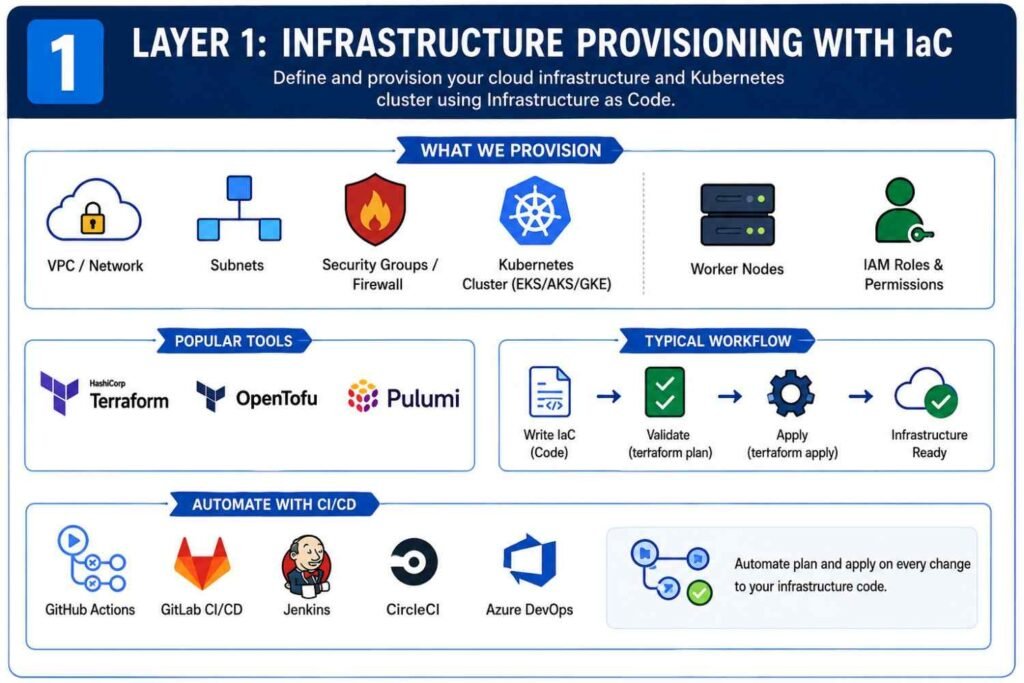
Layer 1: Provisioning Kubernetes Infrastructure with IaC
Before deploying applications, you need the underlying infrastructure.
That includes:
- Virtual networks
- Subnets
- Security groups
- Firewalls
- Load balancers
- Kubernetes clusters
- Cloud IAM roles
Instead of creating these resources manually from a cloud console, I always define them using code.
Choosing an Infrastructure Provisioning Tool
Most DevOps teams use one of these tools:
| Tool | Primary Use |
|---|---|
| Terraform | Multi-cloud infrastructure provisioning |
| OpenTofu | Open-source Terraform alternative |
| Pulumi | Infrastructure using programming languages |
| AWS CloudFormation | AWS-specific provisioning |
| Azure Bicep | Azure infrastructure |
| Google Deployment Manager | Google Cloud provisioning |
For most Kubernetes projects, Terraform remains the most common choice because it works across AWS, Azure, Google Cloud, VMware, and many other platforms.
Define Everything as Code
A typical Terraform project may create:
- VPC networks
- Public and private subnets
- NAT gateways
- Security groups
- Route tables
- EKS, AKS, or GKE clusters
- Worker nodes
- IAM permissions
Instead of clicking buttons inside AWS, you simply commit code like this:
terraform init
terraform plan
terraform apply
The entire infrastructure becomes repeatable.
Need another environment?
Run the same code.
Need disaster recovery?
Use the same code.
Need to rebuild after a failure?
Use the same code.
That’s the beauty of IaC.
Automate Infrastructure Deployment
Most mature teams don’t run Terraform manually.
Instead, they connect Git repositories to CI/CD tools such as:
- GitHub Actions
- GitLab CI/CD
- Jenkins
- CircleCI
- Azure DevOps
Whenever infrastructure code changes, the pipeline automatically validates and deploys the update.
No guessing.
No forgotten steps.
No hidden changes.
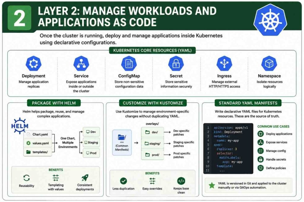
Layer 2: Managing Kubernetes Workloads as Code
Once the cluster exists, the next step is managing everything running inside it.
This is where Kubernetes shines.
Almost everything in Kubernetes can be declared through YAML files.
Using Standard Kubernetes YAML Manifests
Every application starts with core Kubernetes resources.
Common examples include:
| Resource | Purpose |
|---|---|
| Deployment | Runs containers |
| Service | Exposes applications |
| ConfigMap | Stores configuration |
| Secret | Stores sensitive values |
| Ingress | Manages external traffic |
| Namespace | Logical separation |
A Deployment file might define:
- Container image
- CPU allocation
- Memory limits
- Replica count
- Environment variables
Instead of manually scaling or configuring containers, the YAML file becomes the source of truth.
Git stores the configuration.
Kubernetes enforces it.
Package Applications with Helm
As applications grow, raw YAML files become difficult to manage.
I have seen projects with hundreds of YAML manifests spread across multiple folders. Updating them became painful.
This is where Helm helps.
Helm works like a package manager for Kubernetes.
A Helm chart contains:
Chart.yaml
values.yaml
templates/
The templates contain reusable Kubernetes manifests.
The values file contains environment-specific settings.
For example:
Development
replicaCount: 2Production
replicaCount: 10The same chart can deploy both environments by simply changing values.
This reduces duplication and keeps deployments consistent.
Use Kustomize for Lightweight Customization
Not every project needs Helm.
Sometimes you only want small differences between environments.
That’s where Kustomize fits nicely.
I often use Kustomize when:
- Replica counts differ
- Labels change
- Resource limits vary
- Image tags change
A base configuration stays unchanged while overlays apply modifications.
For example:
base/
overlays/dev/
overlays/staging/
overlays/prod/
The result is cleaner than maintaining separate YAML files for every environment.
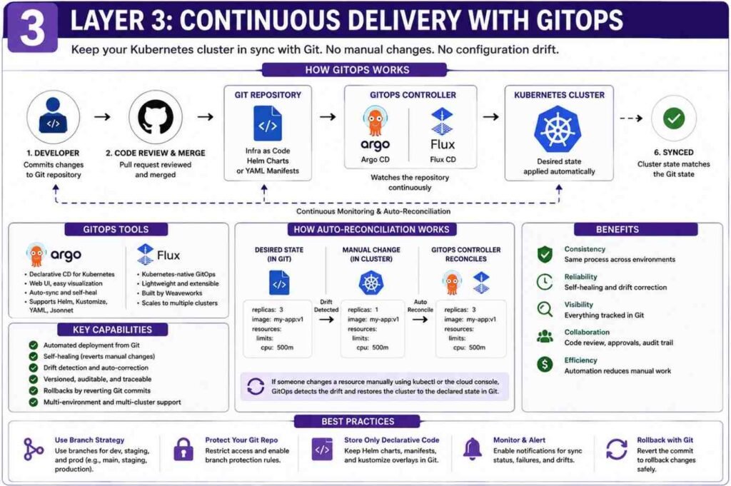
Layer 3: Implement Continuous Delivery with GitOps
One of the biggest problems in Kubernetes environments is configuration drift.
Configuration drift happens when someone changes resources directly inside the cluster.
The Git repository says one thing.
The cluster says another.
Eventually nobody knows which version is correct.
I have seen outages caused entirely by this problem.
GitOps solves it.
Deploy a GitOps Controller
Popular GitOps tools include:
- Argo CD
- Flux CD
These tools run inside Kubernetes itself.
Their job is simple.
Monitor Git repositories continuously.
Whenever a change appears, they apply it automatically.
Connect Git Repositories
The GitOps controller watches repositories containing:
- Helm charts
- YAML manifests
- Kustomize overlays
- Infrastructure definitions
Every change follows a standard process:
- Developer creates code.
- Pull request gets reviewed.
- Code merges into Git.
- GitOps controller detects change.
- Kubernetes updates automatically.
No manual kubectl commands required.
Enable Auto-Reconciliation
This feature is one of my favorites.
Suppose someone manually changes a deployment:
kubectl edit deploymentThe change succeeds.
But a few minutes later, Argo CD notices the cluster no longer matches Git.
It automatically restores the desired state.
The cluster heals itself.
That’s incredibly valuable in production environments.
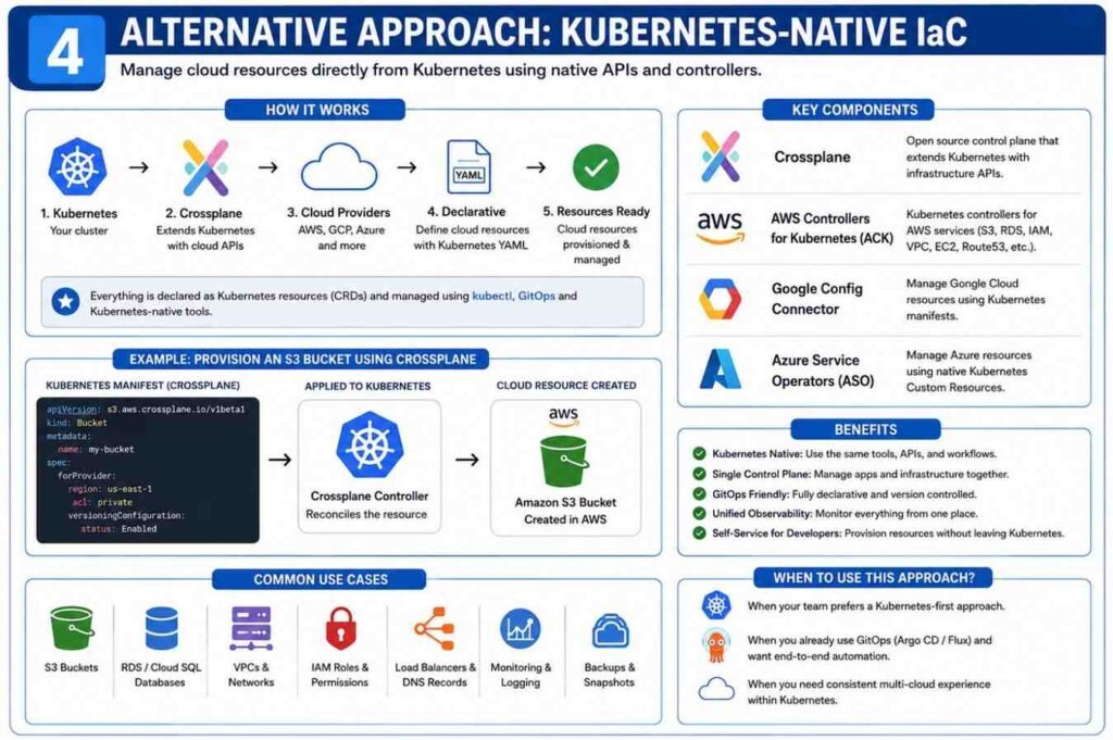
Alternative Approach: Kubernetes-Native Infrastructure
Some organizations want Kubernetes to manage cloud resources too.
Instead of Terraform creating databases and storage buckets, Kubernetes handles them directly.
Use Crossplane
Crossplane extends Kubernetes APIs.
After installation, you can create cloud resources using standard Kubernetes manifests.
For example:
- Databases
- Object storage buckets
- Virtual networks
- Cloud services
Everything becomes Kubernetes-native.
Cloud Provider Controllers
Cloud vendors also provide integrations.
Examples include:
- AWS Controllers for Kubernetes (ACK)
- Google Config Connector
- Azure Service Operators
These tools allow Kubernetes YAML files to provision cloud resources directly.
The experience feels similar to deploying Pods and Services.
Production Best Practices for IaC and Configuration Management
Getting Kubernetes deployments working is one thing.
Running them safely in production is another.
Here are practices I always recommend.
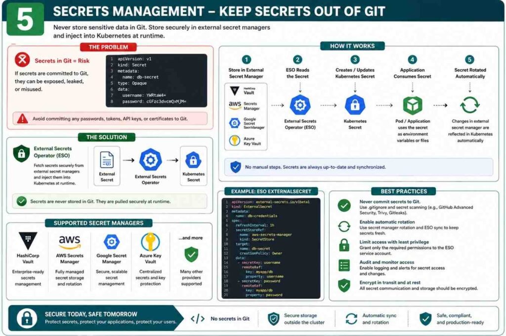
Never Store Secrets in Git
One mistake can expose:
- Database passwords
- API keys
- Access tokens
Use:
- HashiCorp Vault
- AWS Secrets Manager
- Google Secret Manager
- Azure Key Vault
Tools like External Secrets Operator can automatically inject secrets into Kubernetes during runtime.
The sensitive values never live in Git.
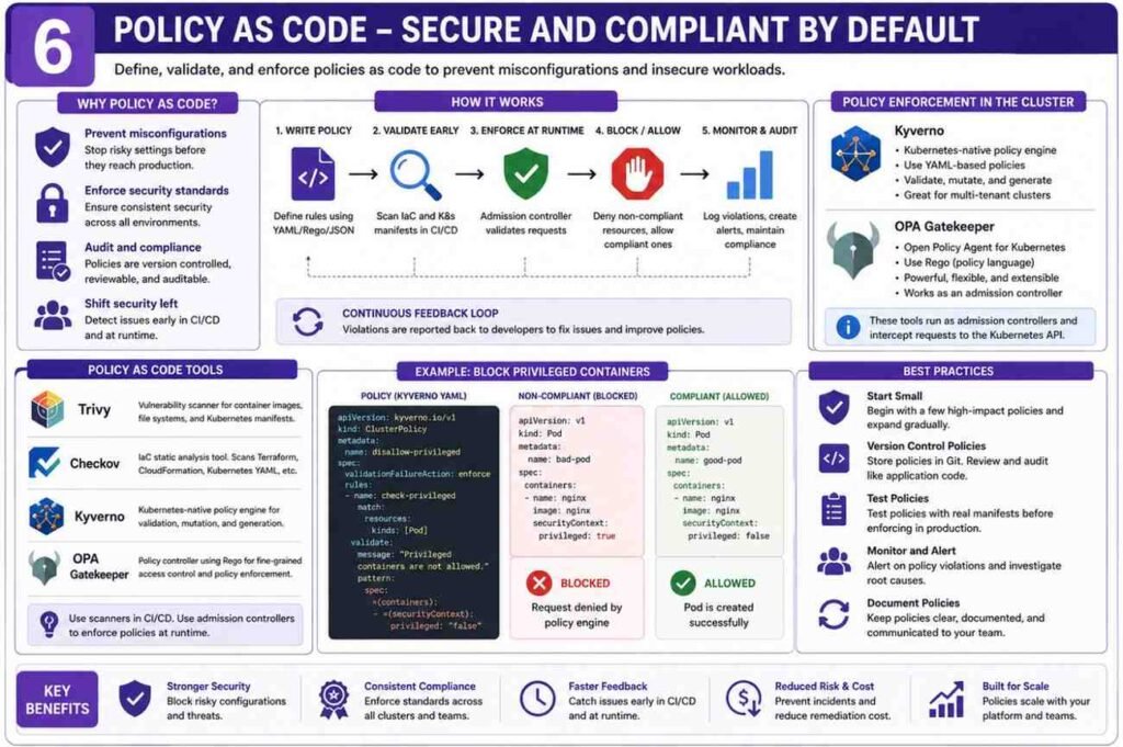
Enforce Policy as Code
Security checks should happen before deployment.
Popular tools include:
| Tool | Purpose |
|---|---|
| Trivy | Vulnerability scanning |
| Checkov | IaC security scanning |
| Kyverno | Kubernetes policy enforcement |
| OPA Gatekeeper | Admission control policies |
These tools block risky configurations before they reach production.
Examples include:
- Privileged containers
- Missing resource limits
- Publicly exposed services
- Insecure permissions
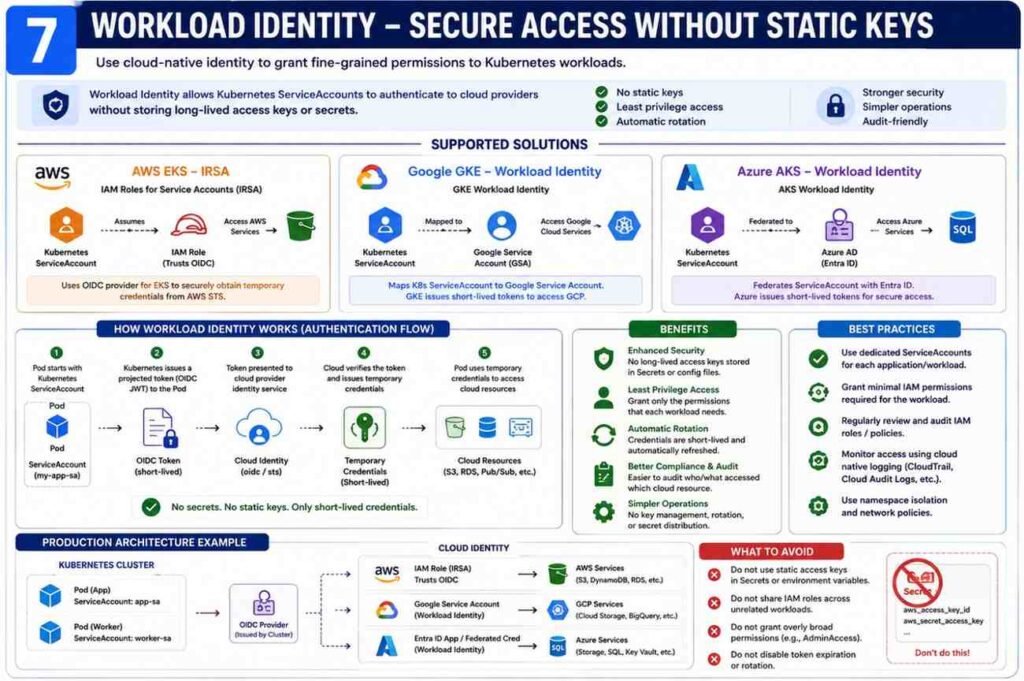
Use Workload Identity Instead of Static Credentials
Many beginners place cloud access keys inside Secrets.
I strongly avoid this.
Modern Kubernetes platforms support identity-based access:
- AWS EKS IRSA
- Google GKE Workload Identity
- Azure AKS Workload Identity
A Kubernetes ServiceAccount maps directly to cloud IAM permissions.
No static credentials.
No key rotation headaches.
Far better security.
Final Thoughts
When I review successful Kubernetes environments, they all share one characteristic: everything lives in Git.
Infrastructure.
Applications.
Policies.
Security controls.
Secrets integration.
Nothing depends on manual changes.
A practical setup usually looks like this:
- Terraform or OpenTofu provisions the cluster.
- Helm or Kustomize manages applications.
- Argo CD or Flux synchronizes deployments.
- External Secrets Operator handles secrets.
- Trivy, Checkov, Kyverno, or OPA enforce security.
Once this foundation is in place, deployments become predictable, recoverable, and much easier to manage—even when your Kubernetes environment grows from a few containers to hundreds of workloads.
Example code for Terraform
1. providers.tf
This file configures the necessary AWS, Kubernetes, and Helm providers. It also uses data sources to automatically pass the newly created EKS cluster credentials into the Kubernetes provider.
terraform {
required_version = “>= 1.5.0”
required_providers {
aws = {
source = “hashicorp/aws”
version = “~> 5.0”
}
kubernetes = {
source = “hashicorp/kubernetes”
version = “~> 2.0”
}
helm = {
source = “hashicorp/helm”
version = “~> 2.0”
}
}
}
provider “aws” {
region = “us-east-1” # Change to your preferred region
}
Data sources to get EKS cluster authentication:
data “aws_eks_cluster” “cluster” {
name = aws_eks_cluster.eks.name
}
data “aws_eks_cluster_auth” “cluster” {
name = aws_eks_cluster.eks.name
}
provider “kubernetes” {
host = data.aws_eks_cluster.cluster.endpoint
cluster_ca_certificate = base64decode(data.aws_eks_cluster.cluster.certificate_authority[0].data)
token = data.aws_eks_cluster_auth.cluster.token
}
provider “helm” {
kubernetes {
host = data.aws_eks_cluster.cluster.endpoint
cluster_ca_certificate = base64decode(data.aws_eks_cluster.cluster.certificate_authority[0].data)
token = data.aws_eks_cluster_auth.cluster.token
}
}
s3.tf
Creates your S3 bucket. (Optional: You can also use this bucket later as a remote state backend.
resource “aws_s3_bucket” “app_bucket” {
bucket = “my-unique-eks-app-bucket-2026” # Must be globally unique
force_destroy = true
}
resource “aws_s3_bucket_versioning” “versioning” {
bucket = aws_s3_bucket.app_bucket.id
configuration {
status = “Enabled”
}
}
vpc.tf
EKS requires subnets across at least two availability zones. Public subnets must be explicitly tagged so the AWS Load Balancer Controller knows where to place internet-facing Application Load Balancers (ALBs).
resource “aws_vpc” “main” {
cidr_block = “10.0.0.0/16”
enable_dns_hostnames = true
enable_dns_support = true
}
resource “aws_internet_gateway” “igw” {
vpc_id = aws_vpc.main.id
}
Public Subnets (For Load Balancer & NAT Gateway):
resource “aws_subnet” “public_1” {
vpc_id = aws_vpc.main.id
cidr_block = “10.0.1.0/24”
availability_zone = “us-east-1a”
map_public_ip_on_launch = true
tags = {
“kubernetes.io/role/elb” = “1” # Crucial tag for ALB discovery
}
}
resource “aws_subnet” “public_2” {
vpc_id = aws_vpc.main.id
cidr_block = “10.0.2.0/24”
availability_zone = “us-east-1b”
map_public_ip_on_launch = true
tags = {
“kubernetes.io/role/elb” = “1”
}
}
Private Subnets (For EKS EC2 Worker Nodes):
resource “aws_subnet” “private_1” {
vpc_id = aws_vpc.main.id
cidr_block = “10.0.3.0/24”
availability_zone = “us-east-1a”
tags = {
“kubernetes.io/role/internal-elb” = “1”
}
}
resource “aws_subnet” “private_2” {
vpc_id = aws_vpc.main.id
cidr_block = “10.0.4.0/24”
availability_zone = “us-east-1b”
tags = {
“kubernetes.io/role/internal-elb” = “1”
}
}
NAT Gateway for Private Worker Nodes internet access:
resource “aws_eip” “nat” {
domain = “vpc”
}
resource “aws_nat_gateway” “nat” {
allocation_id = aws_eip.nat.id
subnet_id = aws_subnet.public_1.id
}
Routing:
resource “aws_route_table” “public” {
vpc_id = aws_vpc.main.id
route {
cidr_block = “0.0.0.0/0”
gateway_id = aws_internet_gateway.igw.id
}
}
resource “aws_route_table” “private” {
vpc_id = aws_vpc.main.id
route {
cidr_block = “0.0.0.0/0”
nat_gateway_id = aws_nat_gateway.nat.id
}
}
resource “aws_route_table_association” “public_1” {
subnet_id = aws_subnet.public_1.id
route_table_id = aws_route_table.public.id
}
resource “aws_route_table_association” “public_2” {
subnet_id = aws_subnet.public_2.id
route_table_id = aws_route_table.public.id
}
resource “aws_route_table_association” “private_1” {
subnet_id = aws_subnet.private_1.id
route_table_id = aws_route_table.private.id
}
resource “aws_route_table_association” “private_2” {
subnet_id = aws_subnet.private_2.id
route_table_id = aws_route_table.private.id
}
4. eks.tf
This creates the EKS Control Plane Cluster and an EC2 Managed Node Group (Worker Nodes).
IAM Role for EKS Cluster Control Plane:
resource “aws_iam_role” “eks_cluster” {
name = “eks-cluster-role”
assume_role_policy = jsonencode({
Version = “2012-10-17”
Statement = [{
Action = “sts:AssumeRole”
Effect = “Allow”
Principal = { Service = “://amazonaws.com” }
}]
})
}
resource “aws_iam_role_policy_attachment” “eks_cluster_policy” {
policy_arn = “arn:aws:iam::aws:policy/AmazonEKSClusterPolicy”
role = aws_iam_role.eks_cluster.name
}
EKS Cluster:
resource “aws_eks_cluster” “eks” {
name = “my-eks-cluster”
role_arn = aws_iam_role.eks_cluster.arn
version = “1.29”
vpc_config {
subnet_ids = [
aws_subnet.private_1.id,
aws_subnet.private_2.id,
aws_subnet.public_1.id,
aws_subnet.public_2.id
]
}
depends_on = [aws_iam_role_policy_attachment.eks_cluster_policy]
}
IAM Role for EC2 Worker Nodes:
resource “aws_iam_role” “nodes” {
name = “eks-node-group-role”
assume_role_policy = jsonencode({
Version = “2012-10-17”
Statement = [{
Action = “sts:AssumeRole”
Effect = “Allow”
Principal = { Service = “://amazonaws.com” }
}]
})
}
resource “aws_iam_role_policy_attachment” “amazon_eks_worker_node_policy” {
policy_arn = “arn:aws:iam::aws:policy/AmazonEKSWorkerNodePolicy”
role = aws_iam_role.nodes.name
}
resource “aws_iam_role_policy_attachment” “amazon_eks_cni_policy” {
policy_arn = “arn:aws:iam::aws:policy/AmazonEKS_CNI_Policy”
role = aws_iam_role.nodes.name
}
resource “aws_iam_role_policy_attachment” “amazon_ec2_container_registry_read_only” {
policy_arn = “arn:aws:iam::aws:policy/AmazonEC2ContainerRegistryReadOnly”
role = aws_iam_role.nodes.name
}
EC2 Node Group (Creates the underlying EC2 instances):
resource “aws_eks_node_group” “private_nodes” {
cluster_name = aws_eks_cluster.eks.name
node_group_name = “private-nodes”
node_role_arn = aws_iam_role.nodes.arn
subnet_ids = [
aws_subnet.private_1.id,
aws_subnet.private_2.id
]
capacity_type = “ON_DEMAND”
instance_types = [“t3.medium”]
scaling_config {
desired_size = 2
max_size = 3
min_size = 1
}
depends_on = [
aws_iam_role_policy_attachment.amazon_eks_worker_node_policy,
aws_iam_role_policy_attachment.amazon_eks_cni_policy,
aws_iam_role_policy_attachment.amazon_ec2_container_registry_read_only,
]
}
5. aws_lb_controller.tf
To handle K8s Ingress resources and spin up an actual AWS Application Load Balancer, you must configure an OIDC Provider and deploy the AWS Load Balancer Controller via Helm.
OIDC Provider to allow K8s service accounts to assume AWS IAM roles (IRSA):
data “tls_certificate” “eks” {
url = aws_eks_cluster.eks.identity[0].oidc[0].issuer
}
resource “aws_iam_openid_connect_provider” “eks” {
client_id_list = [“://amazonaws.com”]
thumbprint_list = [data.tls_certificate.eks.certificates[0].sha1_fingerprint]
url = aws_eks_cluster.eks.identity[0].oidc[0].issuer
}
Fetch the official AWS Load Balancer Controller IAM Policy:
data “http” “aws_lb_controller_policy” {
url = “https://githubusercontent.com”
}
resource “aws_iam_policy” “aws_lb_controller” {
name = “AWSLoadBalancerControllerIAMPolicy”
path = “/”
description = “Policy for AWS Load Balancer Controller in EKS”
policy = data.http.aws_lb_controller_policy.response_body
}
IAM Role for the Controller Service Account:
resource “aws_iam_role” “aws_lb_controller” {
name = “aws-load-balancer-controller-role”
assume_role_policy = jsonencode({
Version = “2012-10-17”
Statement = [{
Effect = “Allow”
Principal = {
Federated = aws_iam_openid_connect_provider.eks.arn
}
Action = “sts:AssumeRoleWithWebIdentity”
Condition = {
StringEquals = {
“${replace(aws_iam_openid_connect_provider.eks.url, “https://”, “”)}:sub” = “system:serviceaccount:kube-system:aws-load-balancer-controller”
}
}
}]
})
}
resource “aws_iam_role_policy_attachment” “aws_lb_controller” {
policy_arn = aws_iam_policy.aws_lb_controller.arn
role = aws_iam_role.aws_lb_controller.name
}
Create Kubernetes Service Account for the Controller:
resource “kubernetes_service_account” “aws_lb_controller” {
metadata {
name = “aws-load-balancer-controller”
namespace = “kube-system”
annotations = {
“://amazonaws.com” = aws_iam_role.aws_lb_controller.arn
}
}
}
Install AWS Load Balancer Controller via Helm:
resource “helm_release” “aws_lb_controller” {
name = “aws-load-balancer-controller”
repository = “https://aws.github.io/eks-charts”
chart = “aws-load-balancer-controller”
namespace = “kube-system”
set {
name = “clusterName”
value = aws_eks_cluster.eks.name
}
set {
name = “serviceAccount.create”
value = “false”
}
set {
name = “serviceAccount.name”
value = kubernetes_service_account.aws_lb_controller.metadata[0].name
}
depends_on = [aws_eks_node_group.private_nodes]
}
6. app_and_ingress.tf
Finally, deploy a sample application, expose it via a Kubernetes Service, and define the Ingress resource. The AWS Load Balancer Controller will notice this resource and automatically spin up a real AWS Application Load Balancer (ALB).
Sample Nginx Deployment:
resource “kubernetes_deployment” “sample_app” {
metadata {
name = “sample-nginx-app”
labels = { app = “nginx” }
}
spec {
replicas = 2
selector { match_labels = { app = “nginx” } }
template {
metadata { labels = { app = “nginx” } }
spec {
container {
image = “nginx:latest”
name = “nginx”
port { container_port = 80 }
}
}
}
}
depends_on = [helm_release.aws_lb_controller]
}
NodePort Service (Required by AWS ALB Ingress):
resource “kubernetes_service” “sample_service” {
metadata {
name = “sample-nginx-service”
}
spec {
selector = { app = “nginx” }
port {
port = 80
target_port = 80
}
type = “NodePort”
}
}
K8s Ingress (Triggers creation of the AWS Load Balancer):
resource “kubernetes_ingress_v1” “app_ingress” {
metadata {
name = “app-ingress”
annotations = {
“kubernetes.io/ingress.class” = “alb”
“alb.ingress.kubernetes.io/scheme” = “internet-facing” # Provisions a public ALB
“alb.ingress.kubernetes.io/target-type” = “ip”
}
}
spec {
rule {
http {
path {
path = “/”
path_type = “Prefix”
backend {
service {
name = kubernetes_service.sample_service.metadata[0].name
port { number = 80 }
}
}
}
}
}
}
}
Deployment Steps:
Put all 6 files in an empty folder.
Initialize the directory: terraform init.
Review what will be built: terraform plan.
Provision everything: terraform apply -auto-approve.
Note: It can take 10 to 15 minutes for the AWS EKS cluster control plane and EC2 node groups to cleanly spin up.Once completed, you can fetch your public ALB URL using the AWS Console or via your local kubectl utility.


Leave a Reply